

Pin placement is identical to the 7-pin ISO 1724 with the absence of these pins. This 5-pin connector has been superseded by the 7-pin (AS 2513), but can be found on older vehicles. Round 5-pin trailer connector Type 1 Round 5-pin trailer connector Type 1
4 PIN TRAILER WIRING DIAGRAM REGISTRATION
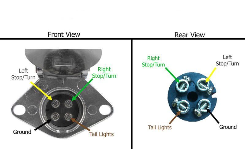
Tail lamps, clearance lamps/outline marker lamps and registration plate lamp left side Reversing lamps, control current to block surge brakes when reversing. Pin 2 (54G) is in the Australian wiring standard the reversing light, which is a minor problem. In this pinout for an ISO 1724 connector, the position light pin is used for electric brakes (Pin 5, 58R), which means that if you connect a trailer with electric brakes to a towing vehicle wired according to ISO 1724 and turn on the position lights the trailer will be braking. Round 7-pin trailer connector Type 1 (AS 2513) Round 7-pin trailer connector Type 1, Australian Standard 2513 These connectors are based on ISO 1724 in 5-pin and 7-pin versions, but with some difference in the wiring. Round trailer connectors Type 1 Round trailer connectors Type 1 Reversing lamps or +12V via ignition lock The voltage varies from vehicle to vehicle.Ĭlearance lamps/Outline marker lamps, Side marker lamps, identification lamps This connector is based on both SAE J560 and ISO 1185 and is providing either 12V, 7 x 40A or 24V, 7 x 20A. Since Australia has vehicles from both the North American market and the European market there is a mixture of 12V and 24V.ħ-pin trailer connector (AS 4735) for heavy duty vehicles 7-pin trailer connector (AS 4735) for heavy duty vehicles (Towing vehicle side) The only connector used on the Australian market that is fully ISO standard conformant is the 7-pin ABS / EBS plug. The Australian market generally uses its own version of the European connectors, as well as its uniquely own contacts. This will help ensure that the connection is safe and secure.A number of standards prevail in Australia for trailer connectors, the electrical connectors between vehicles and the trailers they tow that provide a means of control trailer lamps, and in one case, trailer brakes, and also sometimes, manufacturer-specific non-standard functions. Additionally, the 4 pin trailer wiring diagram should be checked periodically for any corrosion or other damage that may have occurred over time. All of these wires must be properly connected in order for the trailer to function properly. The second wire is for the tail lights and brake lights, the third wire is for the turn signals and side markers, and the fourth wire is for the reverse lights. The first wire is the ground wire, which connects the towing vehicle's frame to the trailer frame. The four wires are typically color coded to help make it easier to understand which wire goes where. It is important to understand how these four wires are connected and how they are used in order to ensure that your trailer is properly wired.

These wires are designed to carry the power from the towing vehicle to the trailer lights, brakes and other accessories. Understanding the basics of the 4 pin trailer wiring diagram will help make sure that you have a safe and secure connection between your trailer and your vehicle.Ī 4 pin trailer wiring diagram is the most common type of wiring for trailers. Trailer wiring has become more and more complex over the years, and understanding 4 pin trailer wiring is one of the most important elements of connecting a trailer to your vehicle.


 0 kommentar(er)
